
CARBOROBOT 120 BIO biomass boiler
Biomass
boilers
For
warm water
- BIO
Automated, pellet, wood chips,
- Farmer
Automated, pellet,wood chips,
wood logs, multifuel
- Automat
Self-loading, automated, pellet, wood chips, multifuel
- Low pressure steam (0,5bar) automated boilers for biomass, pellet, wood chips, multifuel
- Automated brown coal boilers
For warm water or low pressure steam
- Feedlan
control
Solid-fuel handling system
- Moving
floor
Automated solid-fuel store
- Fuel
stores
For solid-fuel
- Augers
- Loader spoon
- Ash
removing
![]()
![]()
| CARBOROBOT 120 BIO | |||||||
|
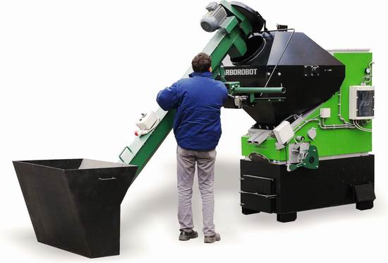
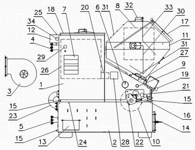
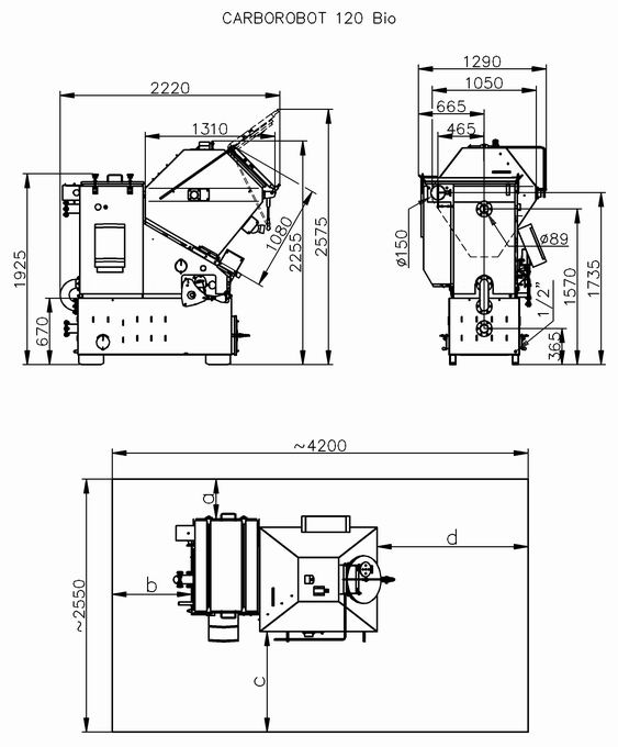
The CARBOROBOT 120 BIO (C120 BIO) automatic biomass multifuel boiler has been developed for providing well controlled continuous heating without the need for an operator being present. It is an ideal choice for locations where biomass fuels are readily available. This boilers are well suited for the heating of houses, blocks of flats, workshops, glass houses, foil tents. A feature of the boiler is the large fuel container mounted on top, that is filled manually or by an auger. With the appropriate fuel, the boiler may operate autonomously even up to few days The cinder is removed manually at the same time as filling the fuel container. The boiler does not need attention while there is fuel in the container because built in sensors control the autonomous operation. The BIO versions have an agitator built into the fuel container to ensure the smooth flow of the various materials. Further accessories of the boiler are a multicyclone module, an exhaust fan, a touch-screen control and an SMS remote control unit. According to operation modes, this is hot water boiler (3bar 95°C). The nominal power is 120kW(105.000kcal/h) what measured with average fuel with 15BTU(17MJ/kg,4000kcal/kg). The ash content of different fuels can be up to 20%!! With separate hot exchanger it also provides domestic hot water. For the installation need standard chimney. The installation has to be carried out following the relevant technical and local regulations. In closed heating systems a safety walve max.3bar is necessary. To use buffer accumulator possible, but not necessary. The CARBOROBOT BIO boilers review.
|
|||||||
Copyright © 2023 CARBOROBOT
Contact informations tel/fax:+36-13852-862
info@carborobot.com