
Steam boilers (BIO)
Biomass
boilers
For
warm water
- BIO
Automated, pellet, wood chips,
- Farmer
Automated, pellet,wood chips,
wood logs, multifuel
- Automat
Self-loading, automated, pellet, wood chips, multifuel
- Low pressure steam (0,5bar) automated boilers for biomass, pellet, wood chips, multifuel
- Automated brown coal boilers
For warm water or low pressure steam
- Feedlan
control
Solid-fuel handling system
- Moving
floor
Automated solid-fuel store
- Fuel
stores
For solid-fuel
- Augers
- Loader spoon
- Ash
removing
![]()
![]()
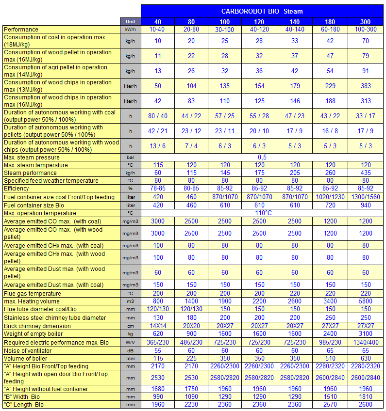
| CARBOROBOT BIO Steam manually feed | |||||||||||||||||||||||||||||||||||||||||
|
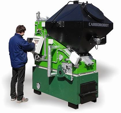
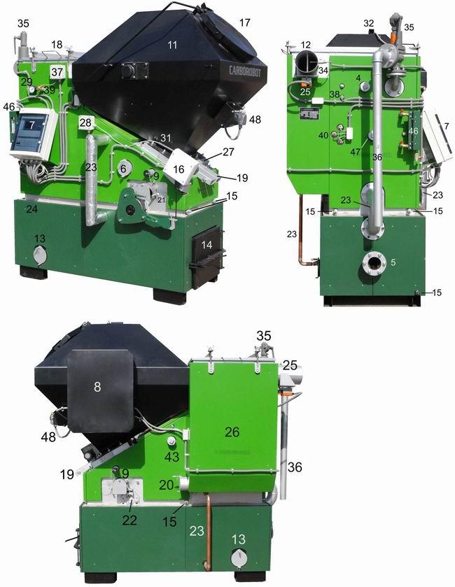
A feature of the CARBOROBOT
BIO Steam boiler is the large
fuel container mounted on top, that is filled manually or by
an auger. With the appropriate
fuel, the
boiler may operate autonomously
even up to few day. It is possible to re-start the boiler without
igniting it again. The ash content of different fuels can be
up to 20%!! The cinder is removed manually at the same
time as filling the fuel container. The boiler does not need
strict attention while there is fuel in the container because
built in sensors control the autonomous operation. The BIO
versions have an agitator built into the fuel container to ensure
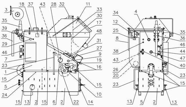
the smooth flow of the various materials. The CARBOROBOT BIO Steam boilers can be used with more types of fuel. This multifuel boilers work on biomass based high ash content agropellet, woodchips, brown coal and of course fruit stones too, which arised as waste. Thermal efficiency of the CARBOROBOT BIO Steam 80-90% and the nominal output power given with the fuel 17MJ/kg(4000kcal/kg) depend on the fuel quality Ideal for use in distillery, distillation, drying plants or other technologies that require low-pressure steam. Mainly they are used in technological processes where there is no need for pressure 0,5bar higher. For heating the building can be used. The optional accessories for
steam boilers feed water preparing system and the pump. The short steam technical info. Fuel is forwarded onto a rotating grate where
it is burnt under automatic control. The boiler operates in
a 3 point switched-mode fashion, i.e. it is can work on 50%
power too. This is controlled by the hetaing technology with
the draft regulator.
When the required steam pressure is reached, the fan stops and
the output power is rapidly reduced to 5-10% of the nominal
value. The fire does not go out even with several hours of waiting,
hence there is no need for a re-ignition unit. When the boiler
switches back on, the full power is reached within a few minutes.
The quoted pellet or coal consumption per hour values refer
to continuous operation. When heat output is not required and
the boiler stops, the fuel consumption becomes negligible. The
fuel consumption is essentially determined by the required energy
output. Experience shows, that approximately 2kg coal or pellets
correspond to 1 m3 of natural gas energy.
|
|||||||||||||||||||||||||||||||||||||||||
Copyright © 2023 CARBOROBOT
Contact informations tel/fax:+36-13852-862
info@carborobot.com